Welcome to SMPI Saturation's documentation!
This page is deprecated. Please see https://gitlab.inria.fr/simgrid/platform-calibration.
We are currently (since 2013… :() trying to strengthen and automate this procedure but we still lack time and manpower.
In the meantime, here is the list of files that can be used for such procedure:
The first time we used this technique was described in our PMBS article on SMPI.
The graphene cluster
The graphene cluster is a Grid'5000 cluster in Nancy. It is organized in 4 irregular cabinets (see Figure). In these experiments, we focused on modeling the behavior of MPI when using the TCP/ethernet network.
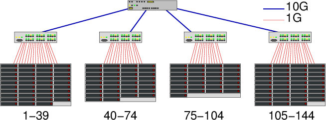
Figure 1: The Graphene organization
On such topology, contention can appear at several points:
- At a node
- Although nodes are equipped with full-duplex 1Gbps links, they are generally unable to reach such capacity. Let's consider two nodes A and B in the same cabinet. Typically, when A sends a large amount of data to B, he gets 96% of the full bandwidth, i.e, around 1000/8×0.96=120 MB/s. The same happens when B sends data to A but when both "A sends data to B" and "B sends data to A", the two communications interfere and the aggregate bandwidth (i.e., the sum of both rates) is rather 160 MB/s (actually 187.5 in this experiment) than 240 MB/s (as could be expected with a full-duplex link). Some contention occurs somewhere at the node level, which is why we model such situation with two links (one for the upload and one for the download, whose rate is 120 MB/s) and a limiter (, whose rate is 160 MB/s). We have thus one such uplink, downlink and limiter for each host (See Figure).
- Inside a cabinet
- Likewise when several pairs of hosts communicate
with each others, there could be contention. To observe such
limitation, we need to have several pairs of hosts communicating
together at the same time. Let's assume that there are \(2n\) nodes
within the cabinet. The set of nodes is divided in two sets
\(\{A_1,\dots,A_n\}\) and \(\{B_1,\dots,B_n\}\) and we measure the aggregate
bandwidth for the following situation (\(\leftrightarrow\) denotes a
MPI_Sendrecvoperation between the two nodes).- \(A_1 \leftrightarrow B_1\)
- \(A_1 \leftrightarrow B_1 || A_2 \leftrightarrow B_2\)
- \(A_1 \leftrightarrow B_1 || A_2 \leftrightarrow B_2 || A_3 \leftrightarrow B_3\)
- …
\(A_1 \leftrightarrow B_1 || A_2 \leftrightarrow B_2 || \dots || A_n \leftrightarrow B_n\)
Intuitively, the aggregated bandwidth is expected to be \(B, 2B, 3B, \dots\) and to possibly reach a plateau. In our case no contention within nodes could be observed, which is why, we did not put any Limiter link inside the cabinets (actually, we did put one in corresponding xml file but its bandwidth was set to 6000000000=6E9, which corresponds to the theoretical capacity).
Note that when looking at the source of alltoall_loadtest.c, one may notice that we used a slightly more complex
MPI_Sendrecvpattern than the one previously mentioned. Instead process are grouped by four and organized as a small ring. The reason why we do that is we noticed there could be some strange serialization phenomenon with simple pairwise send/recv operations that did not allowed us to correctly measure the network capacity of the cabinet.
- Between cabinets
- We use a mixture of the previous approaches as we need to estimate the incoming and outgoing capacity, and the total cross-traffic capacity. Therefore, we consider \(\{A_1,\dots,A_n\}\) (resp. \(\{B_1,\dots,B_n\}\)) the set of nodes from the first (res. second) cabinet. We saturate bandwidth from \(A\) to \(B\) (using send/recv), from \(B\) to \(A\) (using recv/send), and between \(A\) and \(B\) (using SendRecv). In the first two cases, the maximum capacity is 1.16 GB/s and in the last one, the maximum capacity is 1.51 GB/s, which is why each cabinets has its own pair of uplink and downlink with capacity 1.16 GB/S and the four cabinets are connected through a 1.51 GB/s link.
Here is the resulting SimGrid modeling
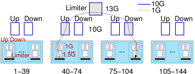
Figure 2: Modeling Graphene contention with SimGrid
In practice, such behavior can thus be represented with the following xml file.


